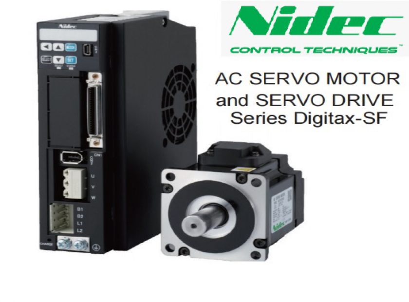
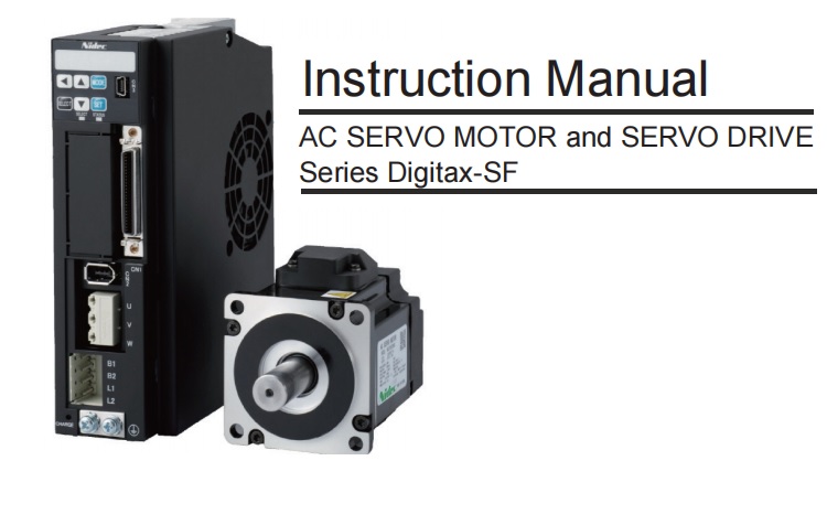
Servo Motor - Servo Driver Control Technique dòng DSF
Servo Motor - Servo Driver Important Safety Instructions
Drives and controllers are intended as components for professional incorporation into complete systems. If installed incorrectly they may present a safety hazard. The drive uses high voltages and currents, carries a high level of stored electrical energy, and is used to control equipment which can cause injury. Close attention is required to the electrical installation and the system design to avoid hazards either in normal operation or in the event of equipment malfunction. System design, installation, commissioning/startup and maintenance must be carried out by personnel who have the necessary training and
competence. They must read this safety information and this guide carefully.
Responsibility
It is the responsibility of the installer to ensure that the equipment is installed correctly with regard to all instructions given in this guide. They must give due consideration to the safety of the complete system, so as to avoid the risk of injury both in normal operation and in the event of a fault or of reasonably foreseeable misuse. The manufacturer accepts no liability for any consequences resulting from inappropriate, negligent or incorrect installation of the equipment.
Compliance with regulations
The installer is responsible for complying with all relevant regulations, such as national wiring regulations, accident prevention regulations and electromagnetic compatibility (EMC) regulations. Particular attention must be given to the crosssectional areas of conductors, the selection of fuses or other protection, and protective ground (earth) connections. This guide contains instructions for achieving compliance with specific EMC standards. All machinery to be supplied within the European Union in which this product is used must comply with the following directives: 2006/42/EC Safety of machinery.
2014/30/EU: Electromagnetic Compatibility.
Electrical Hazards
The voltages used in the drive can cause severe electrical shock and/or burns, and could be lethal. Extreme care is necessary at all times when working with or adjacent to the drive. Hazardous voltage may be present in any of the following locations:
• AC and DC supply cables and connections
• Output cables and connections
• Many internal parts of the drive, and external option units
Unless otherwise indicated, control terminals are single insulated and must not be touched. The supply must be disconnected by an approved electrical isolation device before gaining access to the electrical connections. The control terminal functions of the drive do not isolate dangerous voltages from the output of the drive or from any external option unit. The drive must be installed in accordance with the instructions given in this guide. Failure to observe the instructions could result in a fire hazard.
Stored Electrical Charge
The drive contains capacitors that remain charged to a potentially lethal voltage after the AC supply has been disconnected. If the drive has been energized, the AC supply must be isolated at least ten minutes before work may continue.
Mechanical Hazards
Careful consideration must be given to the functions of the drive or controller which might result in a hazard, either through their intended behaviour or through incorrect operation due to a fault. In any application where a malfunction of the drive or its control system could lead to or allow damage, loss or injury, a risk analysis must be carried out, and where necessary, further measures taken to reduce the risk forexample, an overspeed protection device in case of failure of the speed control, or a failsafe mechanical brake in case of loss of motor braking. None of the drive functions must be used to ensure safety of personnel, i.e. they must not be used for safetyrelated functions. The system designer is responsible for ensuring that the complete system is safe and designed correctly according to the relevant safety standards.
Access to equipment
Access must be restricted to authorized personnel only. Safety regulations which apply at the place of use must be complied with.
Environmental limits
Instructions in this guide regarding transport, storage, installation and use of the equipment must be complied with, including the specified environmental limits. This includes temperature, humidity, contamination, shock and vibration. Equipment must not be subjected to excessive physical force.
Hazardous environments
The equipment must not be installed in a hazardous environment (i.e. a potentially explosive environment).
Motor
The safety of the motor under variable speed conditions must be ensured. To avoid the risk of physical injury, do not exceed the maximum specified speed of the motor.
Mechanical brake control
Any brake control functions are provided to allow well coordinated operation of an external brake with the drive. While both hardware and software are designed to high standards of quality and robustness, they are not intended for use as safety functions, i.e. where a fault or failure would result in a risk of injury. In any application where the incorrect operation of the brake release mechanism could result in injury, independent protection devices of proven integrity must also be incorporated.
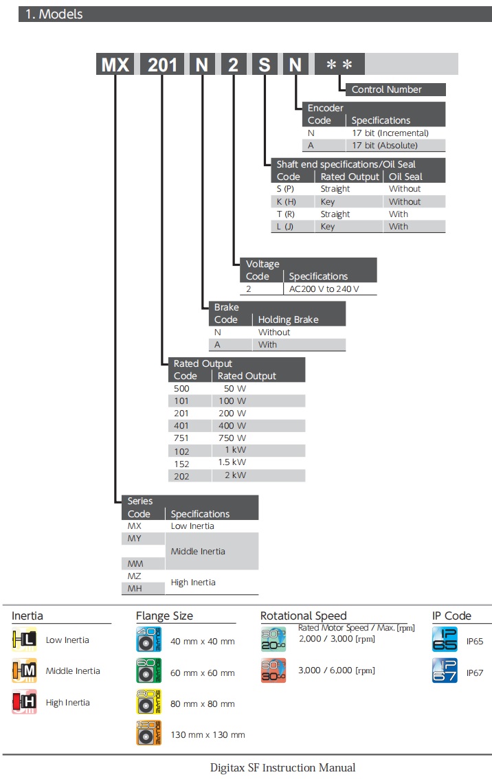
Thông số kỹ thuật chung Servo Motor
| Item | Specifications |
| Ambient temperature for operation | 0 to 40 ℃ |
| Ambient humidity for operation | 20 to 85 %RH (no condensation) |
| Ambient temperature for storage | — 20 to 65 ℃ (no condensation) (not subjected to direct sunlight) 80 ℃ for 72 hours |
| Ambient humidity for storage | 20 to 85 %RH (no condensation) |
| Atmosphere for operation / storage | Indoors(not subject to direct sunlight), Free from corrosive gases, flammable gases, oil mist, dust, flammables, grinding fluid |
| Insulation resistance | ≥ 5 M Ω at 1,000 VDC |
| Dielectric strength | AC 1500 V for one minute across the primary and Ground/Earth FG |
| Operating altitude | ≤ 1,000 m |
| Vibration class | V15 (JEC2121) |
| Vibration resistance | 49 m/s2 (5 G) |
| Impact resistance | 98 m/s2 (10 G) |
| Protective structure | P65:50 W to 750 W IP67:1 kW to 2 kW |
| Electric shock protection | ClassⅠ( Mandatory grounding ) |
| Overvoltage category | Ⅱ |
| Installation environment | Pollution degree 2 |
Thông số kỹ thuật chung Servo Driver
| Item | Specifications | ||||||||
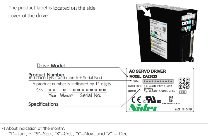
| Model | DA2YZ _ _ | DA2Z1_ _ | DA212_ _ | DA224 _ _ | DA238 _ _ | DA24A _ _ | DA26B _ _ | DA28C _ _ | |
| Compatible Motor | M□500 | M□101 | M□201 | M□401 | M□751 | M□102 | M□152 | MM202 | |
| External dimensions | See "Dimensions" beginning on page 31. | ||||||||
| Weight (kg) | 0.7 | 0.8 | 1.0 | 1.6 | |||||
|
Input power
|
Main circuit power | Single-phase AC200 V to 240 V ± 10 % 50 / 60 Hz |
Three-phase AC200 V to 240 V (*1) ± 10 % 50 / 60 Hz |
||||||
| Control power (*2) | DC24V ±10 % | ||||||||
|
Input current (Arms typ)
|
0.8
|
1.3
|
2.4
|
3.6
|
7.2
|
Single-phase : 9.7 |
6.6
|
9.0
|
|
| Three-phase : 5.1 | |||||||||
|
Control power Current Consumption (mA Typ.)
|
170 | 210 | 260 | 350 | |||||
| Inrush current approx.1.4 A | |||||||||
| Control type Three-phase PWM inverter sine-wave driven | |||||||||
|
Output Rating
|
Rated current(A ) 0.7 | 1.0 | 1.7 | 2.7 | 4.3 | 5.6 | 9.9 | 12.2 | |
| Output frequencies(Hz ) 0 to 500 | 0 to 250 | ||||||||
| Encoder feedback 17 bit single-turn absolute (The product can function as a multi-turn absolute type when batteries are added.) |
|||||||||
|
Control signal
|
Input | 8-point (24 VDC system, opto-coupler input insulation) inputs whose functions are switched by the control mode | |||||||
| Output | 8-point (24 VDC system, open-collector output insulation) outputs whose functions are switched by the control mode | ||||||||
| Analog signal | Input | Single ended (±10 V) input whose functions can be switched by the control mode | |||||||
|
Pulse signal
|
Input
|
RS-422 differential | |||||||
| Open-collector | |||||||||
|
Output
|
Encoder feedback pulse (A-/B-/Z-phase), RS-422 differential output | ||||||||
| Z-phase pulse through open-collector as wel | |||||||||
|
Communication function
|
USB : connection to PC with“Digitax SF Connect”installed | ||||||||
| RS-485 : host remote control communication (multi-drop compatible) | |||||||||
|
Drive status display function
|
Drive status display function 6 digits of seven-segment display on Setup Panel | ||||||||
| Normal/Error display on STATUS LED | |||||||||
| Green light when Power ON Normal, Red light when Power ON Error, Dim when Power OFF | |||||||||
| Regeneration function | A braking resistor may be installed externally (*3) | ||||||||
| Control mode | Position Control, Velocity Control, Torque Control | ||||||||
Environmental Specification
| Environmental Specification | ||
| Item | Specifications | |
|
Ambient
temperature |
For operation | 0 to 50 ℃ (*5) |
| For storage | -20 to 65 ℃ | |
|
Ambient
humidity |
For operation |
20 to 85 % RH(no condensation)
|
| For storage | ||
|
Atmosphere for operation and
storage |
Indoors (not subject to direct sunlight), | |
| Free from corrosive gases, flammable gases, oil mist, dust, flammables, grinding fluid | ||
| Altitude | ≤ 1,000 m | |
|
Vibration
|
≤ 5.8 m/s2(0.6 G) | |
| 10 to 60 Hz (no continuous operation allowed at resonant frequency) | ||
| Dielectric strength | AC 1,500 V for one minute across the primary and Ground/Earth FG | |
| Electric shock protection | ClassⅠ(mandatory grounding) | |
| Overvoltage category | Ⅱ | |
| Installation environment | Pollution degree 2 | |
Drive / Motor Combinations
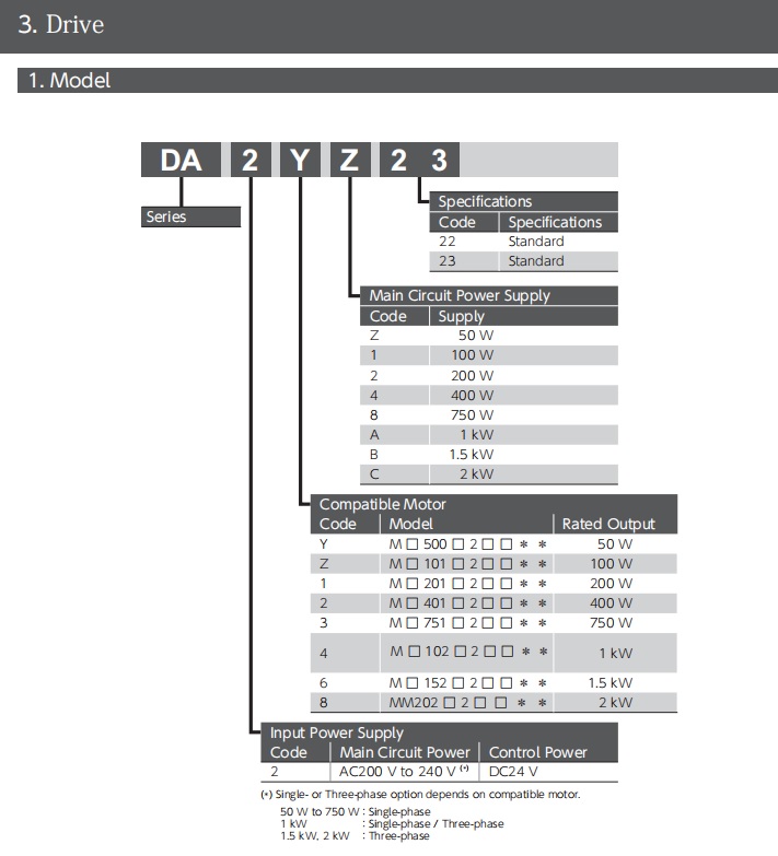
| Drive | Motor | Motor Rated Output Power |
| DA2YZ23 | MY500 □ 2 □□** | 50 W |
| DA2Z123 | MY101 □ 2 □□** | 100 W |
| DA21223 | MX201 □ 2 □□** , MZ201 □ 2 □□** | 200 W |
| DA22423 | MX401 □ 2 □□** , MZ401 □ 2 □□** | 400 W |
| DA23823 | MX751 □ 2 □□** , MZ751 □ 2 □□** | 750 W |
| DA24A23 | MM102 □ 2 □□**, MH102 □ 2 □□** | 1 kW |
| DA26B23 | MM152 □ 2 □□** , MH152 □ 2 □□** | 1.5 kW |
| DA28C23 | MM202 □ 2 □□** | 2 kW |


